
When using a solid modeling CAD package such as Autodesk Inventor or SolidWorks, Flatter Files is able to automatically create all of your assemblies using the model data. This saves an enormous amount of time and has become the most popular feature of our private beta testers. Up to this point, the resulting assembly hierarchies could not be modified in any way since they match the model data unless the assembly was copied and no longer synced to the model data. In addition, only model data that included a matching uploaded drawing was included. It was determined that the flexibility to be able to manually add any existing drawing where the missing drawing should exist would greatly improve the assemblies. Thus, Placeholders have been created to do exactly this.
Before I dive into the details, I want to point out the most common case where this will be very helpful. It is very common that when modeling a part there will be many purchased items that you will want to include. Many times you will download a model from the vendor and include it in your model or you will simply create a model of it yourself. This is very useful to have in the model but the viewers of your drawings need a specification sheet for the item or a simple graphic showing its general dimensions. This information is also typically obtained from the vendor. You can now include this information by simply uploading a PDF of this information and adding it to the location that the placeholder exists. Since you added the item in the model, a Placeholder will now exist in the hierarchy for each of these purchased items.
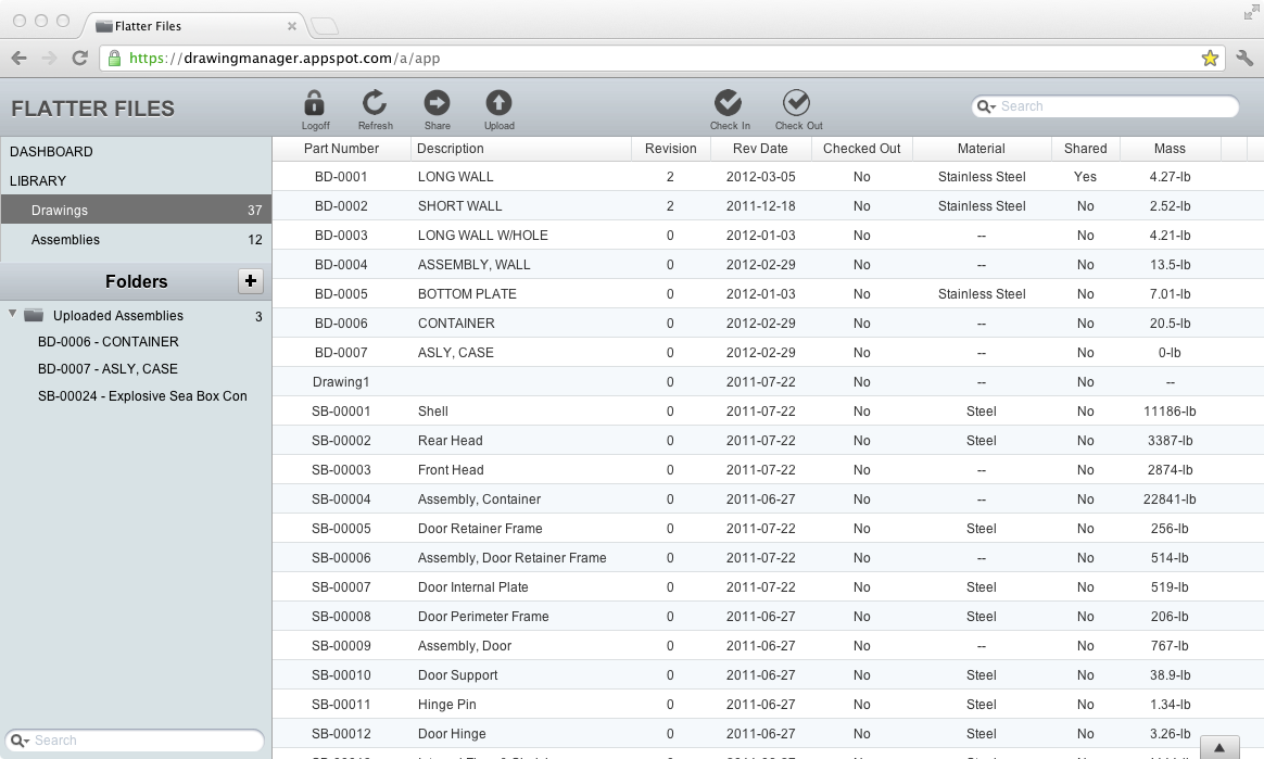
The first view that appears after logging into Flatter Files is shown below. All of your Top Assemblies can be found in the Folders view which is located in the bottom half of the left navigation bar. As you can see in the image, there are currently three Top Assemblies located in the folder Uploaded Assemblies.
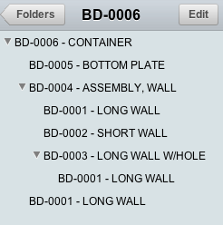
When you click on a Top Assembly, the view transitions to show the hierarchy specific for that Top Assembly. This next image shows a close up of the resulting hierarchy.
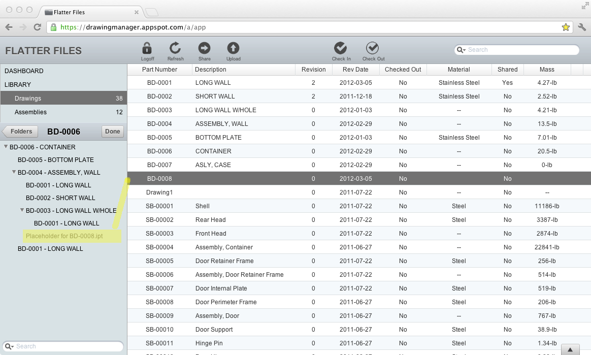
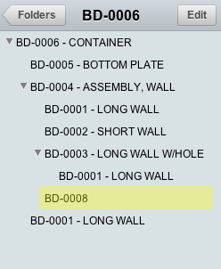
Once you drag the appropriate drawing on the placeholder the assembly will be updated. You now simply click the Done button and the new hierarchy is displayed. The item that has been added is highlighted in the image below.
To remove the item that was added, simply right click and select Delete. This removes the added that was added but does not remove the placeholder. You can easily add another item for the placeholder by simply repeating the steps described above.
Before I dive into the details, I want to point out the most common case where this will be very helpful. It is very common that when modeling a part there will be many purchased items that you will want to include. Many times you will download a model from the vendor and include it in your model or you will simply create a model of it yourself. This is very useful to have in the model but the viewers of your drawings need a specification sheet for the item or a simple graphic showing its general dimensions. This information is also typically obtained from the vendor. You can now include this information by simply uploading a PDF of this information and adding it to the location that the placeholder exists. Since you added the item in the model, a Placeholder will now exist in the hierarchy for each of these purchased items.
The first view that appears after logging into Flatter Files is shown below. All of your Top Assemblies can be found in the Folders view which is located in the bottom half of the left navigation bar. As you can see in the image, there are currently three Top Assemblies located in the folder Uploaded Assemblies.
When you click on a Top Assembly, the view transitions to show the hierarchy specific for that Top Assembly. This next image shows a close up of the resulting hierarchy.
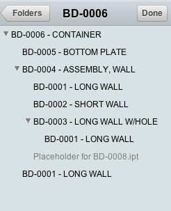
Now that you are viewing this hierarchy, you can simply select any item in the hierarchy to display the complete assembly. By clicking on a specific item within the hierarchy the assembly view will navigate to the particular page containing that drawing within the assembly. A button now appears that is labeled with the Edit button. By clicking this, you now proceed into edit mode which is shown in the image below.
As you can see in the image, a new item within the hierarchy appears that is labeled as a placeholder. This items appears exactly as it does in the model that it was uploaded from. For this particular item though there was not a matching drawing. Therefore, it is displayed as a placeholder in the edit mode. Any drawing in your library can now be dragged onto the Placeholder item. The image highlights the drawing that is added to the hierarchy at the location of the placeholder.
To remove the item that was added, simply right click and select Delete. This removes the added that was added but does not remove the placeholder. You can easily add another item for the placeholder by simply repeating the steps described above.